Introduction
The use-case presented here is a system redesign of a Motor Control Platform where an existing microcontroller (MCU) is to be replaced by a new RISC-V core. Replacing a core component of an industrial embedded systems usually requires huge efforts regarding verification and validation of the new setup. Especially replacing the MCU normally entails significant changes to the hardware/software interface design and the verification process, possibly including the purchase of expensive design IP and verification IP for the specific component. To achieve a shift-left of the system verification, a Virtual Prototype of the system is created to detect possible issues as early as possible during this redesign process long before the real hardware is available. In this way, an early feasibility study can be started independent from the hardware redesign process. Moreover, it helps to analyze and elaborate details of the system requirements, supports the creation of the firmware, and helps to build test scenarios for the final hardware/software components. In this article we will show how to build a Digital Twin of the new system and how to apply dynamic fault-injection for stress-testing the new platform. The effect of various safety-features and redundancy configurations can thus be evaluated and taken into consideration for the full system design.
Use Case Description
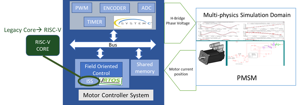
The embedded system shown in Figure 1 that we will apply our methodology to, is an electric motor controller, where a field-oriented control (FOC) algorithm controls the operation of a permanent magnet synchronous motor (PMSM). Tightly time interaction between the control software with the peripherals and external system components imposes real-time constrains on this system. The objective of the example use-case is to analyze the implications of replacing an existing legacy MCU by a new RISC-V core. Due to a hierarchy of timing requirements from the PMSM system application down to the embedded system, the control algorithms must run with a cycle time in the magnitude of microseconds.

Figure 1: Digital Twin of the system-level hardware architecture.
Modelling approach
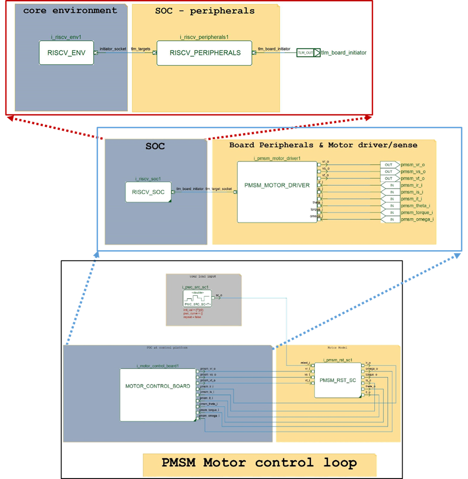
The Digital Twin of the complete motor control system serves as the basis for our virtual stress-testing with dynamic fault-injection. The system model features a motor control board including many peripherals and including the PMSM motor, which together represents the virtual platform of the motor control system. Our modeling language is C++/SystemC/SystemC AMS. The system hierarchy as created within the SystemC AMS modeling IDE COSIDE is depicted in Figure 2.

Figure 2: Hierarchical architecture schematic used within the Digital Twin.
The main goal of such an investigation is to analyze the implications of replacing the MCU within this system. In comparison to the original model, the new design will include a RISC-V SoC instead of a legacy core. In order to run the FOC application on the RISC-V instruction set simulator, some changes need to be made before cross-compiling the old code for the new target architecture.
The essence of the FOC algorithm is to calculate the 3-phase motor voltages based on the motor currents, evaluate the motor position, and calculate the requested rotation speed of the motor. Additionally, the controller must be able to compensate influences e.g. of load changes. Before analyzing any performance parameters of the real-time system, the correct basic functionality of the controller has to be evaluated.
Dynamic fault-injection
Clearly, a real-world system as the one presented here is not working in a perfect environment, but is influenced by many environmental factors, reliability issues, and random failures. A variety of potentially safety-critical faults with possibly severe consequences can occur. The designer of safety-critical systems therefore is responsible for examining which faults have a high probability of occurrence and a significant impact. On this basis, corresponding counter measures, i.e. safety mechanisms, have to be developed and deployed.
Ideally, the system is able to compensate for all uncertainties and can guarantee the function in any situation. However, every system has limited parameter space within which the regular function can be guaranteed. In cases where the system is not able to compensate a critical state, a safety mechanism has to detect the fault within the Fault Detection Time Interval (FDTI) and bring the system back into a safe state. The evaluation of such safety mechanisms should be done as early as possible during the design process. A simulation-based approach is ideally suited for risk-free investigations of potential harmful states and avoids damages to the real system.
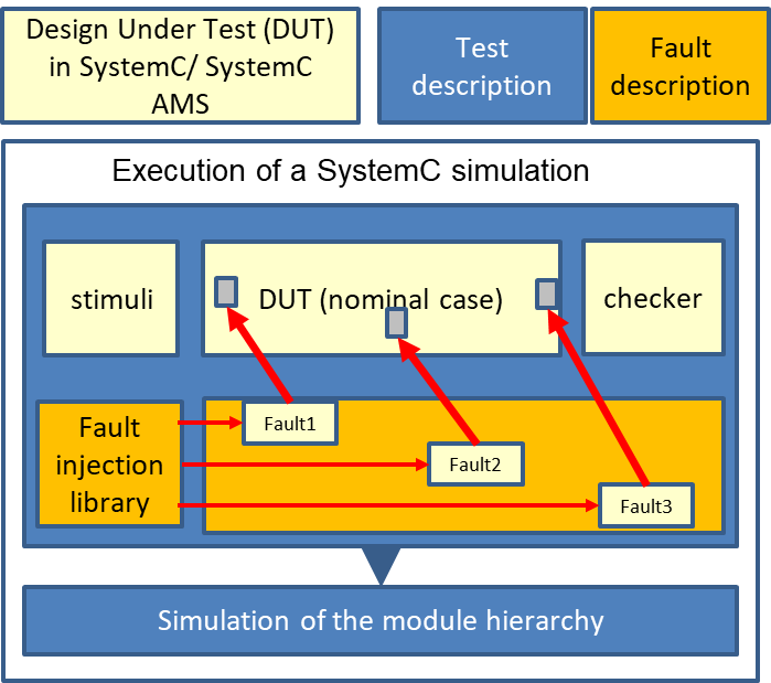
The approach of dynamic fault-injection is a methodology which allows to inject faults into arbitrary parts of the model during runtime without the need to change the design under test (DUT). For this, the faults are not part of the DUT but of the testbench instead. Faults are only injected during the execution of the fault simulation, while the DUT can remain in its nominal, fault-free form.
Figure 3 shows the general principle of our injection approach. During the elaboration phase of the fault simulation, runtime in-memory connections in the netlist are disconnected and new structures are inserted which allow to switch between faultless and faulty behavior.

Figure 3: General concept sketch of the dynamic fault-injection approach.
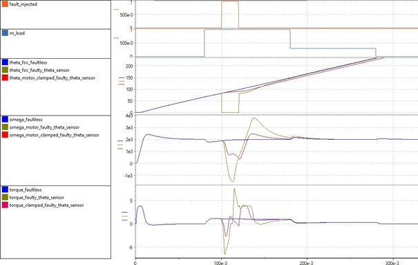
Figure 4 compares the simulation results of three different color-coded scenarios within one diagram:
In blue color, the fault-free simulation results for the nominal case are shown. It can be observed that the FOC ramps up the motor speed to the desired target value, which is 2000 RPM. The algorithm is able to compensate step-changes of the motor’s torque load and drives the motor back to the user-requested rotational speed.
Signals in green show simulation results with a short disruption of the encoder signal, i.e. the motor angle sensor signal. It can be seen that the control algorithm is able to compensate this instability caused by the missing signal for a very short time interval. If the signal was absent for longer, the system’s instability becomes larger and the algorithm is not able to compensate it anymore. For a real system, this may result in damages or the destructions.
Finally, we show the result of an implemented safety mechanism that detects such an encoder defect and uses the last valid signal value for the missing signal. Signals in red show the result with such a safety mechanism in place.

Figure 4: Comparison between the fault-free scenario in blue, the faulty scenario in green, as well as the faulty scenario with a software-based safety mechanism in red.
Such fault simulations using a Digital Twin can be used to detect e.g. the maximal tolerable time interval for the missing sensor signal without risking any damage to a real hardware. Moreover, different safety mechanisms and parameters can be evaluated, compared and optimized.
Summary
In this article, we presented a stress-testing methodology based on virtual prototypes and dynamic fault-injection that simplifies the hardware exploration process when designing real-time application systems. The virtual cyber-physical system helps to identify issues with the application software long before an intended redesign. Reuse of test cases through the concept exploration phase allows to continuously refine requirements and generate testbenches for a test framework. This could be reutilized in the next stage for RTL design verification as a golden reference and extend the coverage metrics with system level stimulus.
References
[1] J. Santana, G. Pachiana, T. Markwirth, C. Sohrmann, B. Fischer, M. Matschnig, „Evaluating the suitability of a RISC-V core for real-time applications using a virtual prototype”, DVCon US 2022
[2] G. Pachiana, M. Grunwald, T. Markwirth, C. Sohrmann, “Automated traceability of requirements in the design and verification process of safety-critical mixed-signal systems”, DVCon US 2020.
[3] T. Markwirth, R. Jancke and C. Sohrmann, “Dynamic fault injection into digital twins of safety-critical systems,” 2021 Design, Automation & Test in Europe Conference & Exhibition (DATE), 2021, pp. 446-450, doi: 10.23919/DATE51398.2021.9474066.
[4] M. Ishikawa, D. McCune, and G. Saikalis, “CPU Model-based Hardware/Software Co-design, Co-simulation and Analysis Technology for Real-time Embedded Control Systems” RTAS’07.

Thomas Markwirth holds a Diploma in Microsystems Technology from the University of Applied Sciences Mittweida and a Diploma in Electrical Engineering from the Technical University of Dresden. He is working as an engineer of Fraunhofer IIS/EAS in Dresden, Germany, since 2002. In this function he is entrusted with mixed-signal/mixed-domain modeling of electronic systems by using hardware description languages such as SystemC/SystemC AMS, VHDL-AMS or Verilog-AMS. He was involved in various research and development projects, most of them with an industrial focus.

Dr. Christoph Sohrmann received his B.Sc. degree from Chemnitz University of Technology, Germany, in 2003, and his Ph.D. in theoretical physics from the University of Warwick, UK, in 2007. He then joined the Fraunhofer Institute for Integrated Circuits IIS, Division Engineering of Adaptive Systems EAS in Dresden, Germany. He is now heading the research group Virtual System Development where he is managing a team of researchers in the field of design methods for electronic systems. His research focus is on virtual prototyping and modelling of electronic systems to simplify the V&V process while increasing robustness and reliability.

Bernhard Fischer graduated in computer science at the Vienna University of Technology in 2011. Since joining Siemens AG (R&D department for Electronic Design, Vienna) in 2011, he has been working in the fields of Electronic System Level Modelling, High-Level Power Modelling, Dependability Co-Engineering, Design Flows, and Formal Verification. He contributed to various industrial projects and EU-funded research projects in the Industrial domain.
